The Science of Cap Ejection Pin Placement

Ejector pins seem simple. They are just steel rods that push the cap off the core. What could be complicated about that?
Everything.
Where the pins are placed determines whether the cap ejects straight or tilts. Whether the force is distributed evenly or concentrated. Whether the cap deforms or remains round. Whether ejector pin marks are visible or hidden. Whether the cap sticks or releases cleanly.
Ejector pin placement is not an afterthought. It is a science that requires careful calculation, symmetry analysis, force distribution modeling, and aesthetic consideration.
At Shuanghao, we treat ejector pin placement as a critical engineering discipline. This article reveals the principles and methods behind optimal ejection pin layout for bottle cap molds.
The Physics of Ejection
Before discussing pin placement, it is essential to understand what happens during ejection.
The Forces at Work
When the mold opens, the cap is shrink-fit onto the core. The plastic has contracted as it cooled, gripping the core tightly. The ejection system must overcome this grip force.
The grip force depends on material shrinkage (1-2% for PP, 1.5-2.5% for HDPE), core surface finish (smoother = less grip), draft angle (more draft = less grip), and cooling time (longer cooling = more grip).
Ejection force must overcome friction between cap and core. It must also break any vacuum seal between cap and core.
Consequences of Poor Placement
If pins are placed asymmetrically, the cap will tilt during ejection, causing uneven wall thickness and potential sticking. If pins are too few or too small, force concentration will deform the cap and create deep ejector pin marks. If pins are placed on visible surfaces, marks will be visible to consumers. If pins miss the cap rim, they will damage the cap or miss entirely.
Fundamental Principles of Pin Placement
Shuanghao follows several fundamental principles for ejector pin placement.
Principle 1: Symmetry
Pins must be placed symmetrically around the cap circumference. Symmetry ensures even force distribution. Even force prevents tilting. Tilting causes deformation and uneven ejection.
For round caps, pins are equally spaced around the circle. For a 4-pin layout, pins at 0°, 90°, 180°, 270°. For a 6-pin layout, pins at 0°, 60°, 120°, 180°, 240°, 300°.
Principle 2: Rim Placement
Pins should contact the cap at its strongest point: the rim. The cap rim has the thickest cross-section. It is the most rigid part of the cap. Pushing on the rim distributes force without deformation.
Pins placed on the sidewall or top panel will deform the cap.
Principle 3: Hidden Placement
Pins should be placed where marks will not be visible. Under the tamper-evident band is ideal. Inside the cap (interior surface) is acceptable for many applications. On the top panel is never acceptable for cosmetic caps. On the sidewall is generally unacceptable.
Principle 4: Sufficient Pin Count
More pins mean lower force per pin. Lower force per pin means shallower marks and less deformation. Shuanghao recommends 4-6 pins for 28mm caps, 6-8 pins for 38mm caps, and 8-12 pins for 48mm+ caps.
Principle 5: Optimal Pin Size
Larger diameter pins distribute force over greater area. Greater area reduces pressure (force/area). Lower pressure reduces mark depth and deformation risk.
Shuanghao uses the largest pin diameter that fits within available space.
Calculating Pin Placement
Pin placement requires systematic calculation.
Step 1: Determine Required Ejection Force
Ejection force can be estimated based on material, cap geometry, and core design. Shuanghao uses empirical formulas and FEA simulation to calculate required force.
For a typical 28mm PP cap, required ejection force is approximately 100-200 Newtons per cavity.
Step 2: Select Pin Count and Size
Select pin count and diameter to keep force per pin below 30-40 Newtons. Force per pin = total ejection force / number of pins. For 200 Newtons total, 6 pins = 33 Newtons per pin. 8 pins = 25 Newtons per pin.
Step 3: Calculate Pin Contact Area
Contact area = pin cross-sectional area. For a 4mm diameter pin, area = 12.6 mm². For a 6mm diameter pin, area = 28.3 mm². Larger area reduces pressure for the same force.
Step 4: Verify Stress
Stress (pressure) on cap = force per pin / contact area. Target stress below 5-10 MPa to prevent deformation.
Step 5: Layout Symmetrically
Place pins at equal angular spacing. Verify no pin interferes with other mold components (slides, lifters, cooling lines).
Pin Placement for Different Cap Types
Round Standard Caps (28mm, 38mm)
For round standard caps, Shuanghao uses 4-6 pins equally spaced. Pins are placed under the tamper-evident band where marks are hidden. Pin diameter is 4-6mm.
Oval and Non-Round Caps
For oval caps, pins must be placed strategically. More pins are typically required than for round caps. Pins are placed at corners and along long edges. Force distribution is more critical because oval caps are less rigid.
Shuanghao uses FEA to optimize pin placement for oval caps.
Thin-Walled Caps
For thin-walled caps, sleeve ejectors are preferred over pins. Sleeves distribute force across the entire rim circumference. If pins must be used, more pins (8-12) with larger diameters are used.
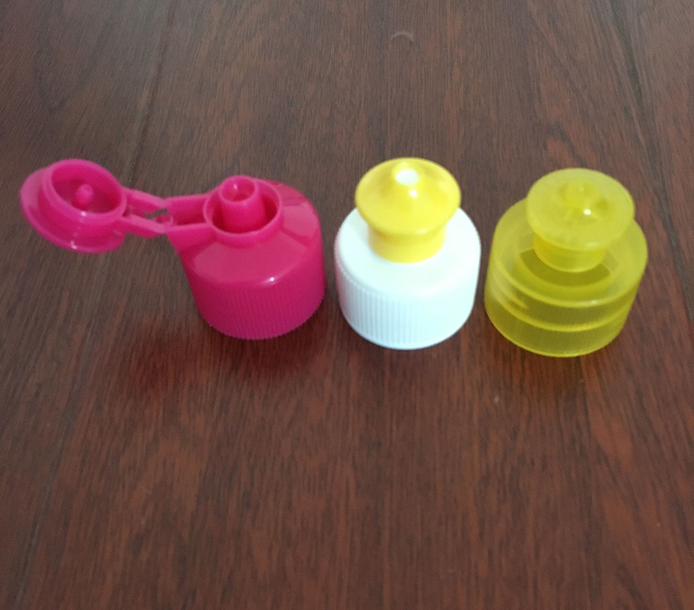
High-Gloss Cosmetic Caps
For high-gloss cosmetic caps, pins cannot be used on visible surfaces. Sleeve ejectors or air ejection are used. If pins must be used, they are placed under the cap (interior) or on non-visible edges.
Child-Resistant Caps
For child-resistant caps with push-and-turn mechanisms, pin placement must avoid interfering with ratchet features. Pins are placed on the outer rim, not on the ratchet surface. Pin marks must not affect mechanism function.
Pin Size Selection
Pin diameter significantly affects ejection performance.
Small Pins (2-3mm)
Small pins are used only when space is extremely limited. They produce deeper marks. They risk cap deformation. They should be avoided when possible.
Medium Pins (4-5mm)
Medium pins are the standard for most caps. They balance space constraints and mark depth. They are suitable for 28-38mm caps.
Large Pins (6-8mm)
Large pins are preferred for minimal marking. They require more space. They are suitable for 48mm+ caps and cosmetic applications.
Sleeve Ejectors vs. Pin Ejectors
Sleeve ejectors are often superior to pin ejectors.
How Sleeve Ejectors Work
A sleeve ejector is a tubular component that surrounds the core. It pushes the entire cap rim simultaneously. Force is distributed evenly around the full circumference. There are no discrete contact points.
Sleeve ejectors leave no visible marks. They produce no deformation (even force distribution). They are ideal for high-gloss cosmetic caps and thin-walled caps.
However, sleeve ejectors are more expensive than pin ejectors. They require more complex mold design. They are not suitable for caps with undercuts.
When to Use Pins vs. Sleeves
Pins are suitable for standard caps where marks are hidden (under TE band). They are appropriate for high-volume production where cost matters. They work for most beverage and industrial caps.
Sleeves are required for high-gloss cosmetic caps (no marks allowed). They are preferred for thin-walled caps (deformation risk). They are suitable for pharmaceutical caps (sterile surfaces).
Air Ejection as an Alternative
Air ejection uses compressed air to lift the cap off the core.
How Air Ejection Works
Compressed air is introduced between cap and core through small passages. Air pressure breaks the vacuum and reduces friction. The cap is lifted slightly, reducing required ejector force. Pins or sleeves complete the ejection.
Air ejection reduces required mechanical force. It minimizes mark depth and deformation risk. It is especially effective for deep caps or sticky materials.
However, air ejection requires additional mold complexity (air passages, valves). It may not be suitable for all cap designs.
Shuanghao often combines air ejection with pins or sleeves for optimal results.
Common Pin Placement Problems and Solutions
Problem: Cap Tilts During Ejection
Tilting indicates asymmetrical pin placement or stuck pins. Solutions include verifying pin symmetry, checking that all pins move freely, ensuring pins are same length, and adding pins if needed.
Problem: Visible Ejector Pin Marks
Visible marks indicate pins too small, pins in wrong location, or excessive ejection force. Solutions include using larger diameter pins, relocating pins to hidden areas (under TE band), reducing ejection force (better draft, smoother core), or switching to sleeve ejectors.
Problem: Cap Deformation
Deformation indicates too few pins, pins too small, or excessive ejection force. Solutions include adding more pins, increasing pin diameter, reducing ejection force, or switching to sleeve ejectors.
Problem: Inconsistent Ejection
Some cycles eject cleanly, others stick. Indicates pin binding or ejection plate issues. Solutions include checking pin lubrication, verifying ejector plate moves freely, inspecting for bent pins, and checking for contamination.
Real-World Results: Shuanghao Pin Placement
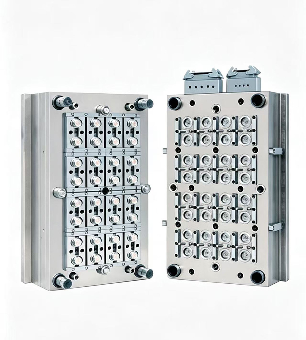
Customer Case: 72-Cavity Water Bottle Cap
A water bottle cap manufacturer had visible ejector pin marks on caps. Pins were placed on the cap interior, visible when consumers opened the bottle.
Shuanghao relocated pins under the tamper-evident band where marks are hidden. Pin diameter was increased from 3mm to 5mm. Mark visibility was eliminated. Consumer complaints dropped to zero.
Customer Case: High-Gloss Cosmetic Cap
A cosmetic cap required absolutely no visible ejector pin marks. The cap had no tamper-evident band to hide pins.
Shuanghao designed a sleeve ejection system. The sleeve pushed the entire cap rim with no discrete contact points. Ejector pin marks were eliminated entirely. The customer achieved the premium appearance required.
The Shuanghao Ejection Pin Placement Advantage
Shuanghao's scientific approach to ejector pin placement provides symmetry analysis for even force distribution. Rim placement where the cap is strongest. Hidden placement to eliminate visible marks. Sufficient pin count calculated by ejection force requirements. Optimal pin size selection for minimal marking. Sleeve ejector alternatives for cosmetic and thin-wall applications. Air ejection integration for reduced force and mark depth.
Conclusion: Small Pins, Big Impact
Ejector pins are small components, but their placement has a massive impact on cap quality. Wrong placement creates visible marks, deformation, and ejection problems. Right placement produces clean, mark-free ejection cycle after cycle.
Shuanghao's scientific approach to ejector pin placement ensures symmetrical layouts, rim contact for strength, hidden placement for aesthetics, sufficient pins for force distribution, and optimal sizing for minimal marks.
Whether you produce beverage caps with hidden TE bands or cosmetic caps requiring zero marks, Shuanghao has the ejection pin placement expertise to deliver clean, non-deforming ejection.
Choose Shuanghao. Choose the science of ejection.