Cooling Channel Pressure Loss Optimization: Achieving Uniform Mold Surface Temperature
Cooling Channel Pressure Loss Optimization: Achieving Uniform Mold Surface Temperature
Published by cap-molds — Leading China Bottle Cap Mold Manufacturer & High-Cavitation Closure Tooling Specialist
1. Introduction: The Thermal Uniformity Paradox in High-Cavitation Tooling
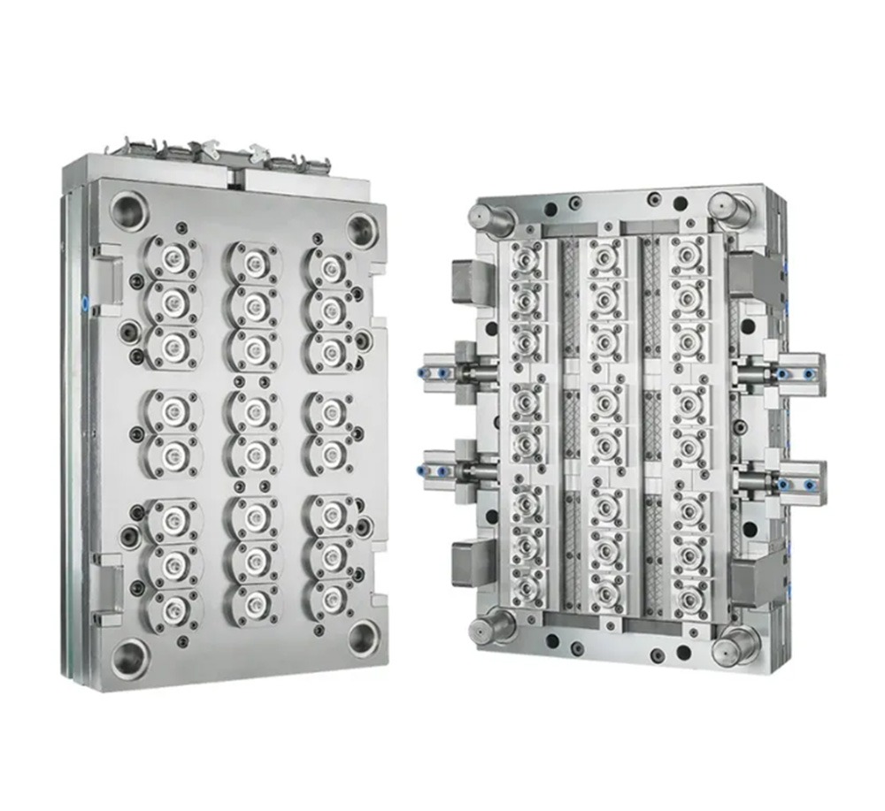
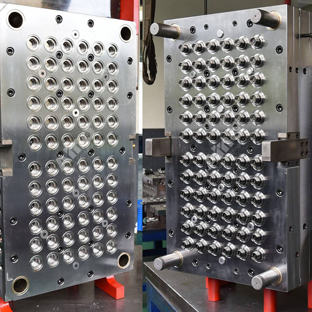
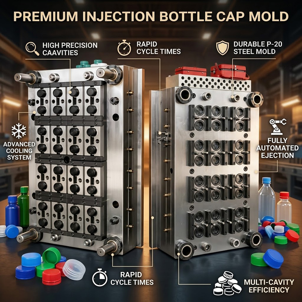
In high-speed bottle cap injection molding, maintaining a strictly uniform mold surface temperature across all cavity drops is critical for dimensional consistency, fast cycle times, and minimal warpage. However, as mold cavity counts increase to 48, 64, or 96 drops, the cooling circuit geometry becomes highly complex. Uncontrolled fluid friction and cumulative pressure loss within intricate channel networks lead to uneven coolant flow distribution.
When pressure drops unevenly across parallel cooling circuits, peripheral cavities receive insufficient flow velocity, leading to thermal hot spots, localized mold expansion, and cap weight variations. As a dedicated expert in precision packaging molds, cap-molds utilizes advanced computational fluid dynamics (CFD) and hydraulic flow balancing to optimize pressure loss, guaranteeing uniform surface temperatures across every single cavity.
2. Physics of Hydraulic Pressure Loss and Thermal Dissipation
Fluid dynamics within mold cooling channels are governed by the Darcy-Weisbach equation and convective heat transfer principles. The pressure loss ($\Delta P$) in a cooling loop depends directly on channel length, equivalent hydraulic diameter, friction factor, and coolant velocity squared.
Key Factors Driving Flow Imbalance in Cap Molds:
- Sharp Bends and Right-Angle Junctions: Traditional drilled cooling channels feature sharp 90-degree intersections that generate excessive secondary flow vortices and localized head loss.
- Cross-Sectional Area Variations: Sudden transitions between main supply manifolds and internal micro-channels cause flow separation and uneven hydraulic resistance.
- Laminar Boundary Layer Isolation: Excessive pressure drop often forces molders to lower pump pressure, causing coolant velocity to fall below the turbulent threshold (Reynolds Number Re < 4,000) and sharply reducing heat transfer efficiency.
3. Hydraulic Optimization Strategies Engineered by cap-molds
To eliminate thermal gradients without overwhelming factory thermolators, cap-molds re-engineers internal cooling geometries using smooth curved transitions, additive manufacturing, and balanced circuit topology.
| Fluid Engineering Parameter | Standard Drilled Cooling System | cap-molds Optimized Hydraulic Architecture |
|---|---|---|
| Channel Junction Geometry | 90° bored right-angle intersections | Smooth swept radii and CFD-optimized teardrop bends |
| Circuit Pressure Drop ($\Delta P$) | High cumulative loss (>2.8 bar per circuit) | Minimised pressure drop (<1.1 bar per circuit) |
| Coolant Flow Regime | Inconsistent transitional flow | Stable Turbulent Flow (Re > 4,500) in all drops |
| Cavity Surface ΔT | Variations up to ±6.5°C across cavities | Strict surface uniformity within ±0.8°C |
4. CFD Modeling & Balanced Multi-Loop Architecture
Before cutting steel, cap-molds engineers perform conjugate heat transfer (CHT) and multi-phase fluid simulations to balance flow impedance across all manifold branches:
- Equi-Resistance Circuit Routing: Coolant path lengths and channel diameters are dynamically sized so that every parallel loop presents identical hydraulic impedance.
- Additive DMLS Conformal Geometry: Utilizing Direct Metal Laser Sintering allows for gradual channel transitions that maintain optimal flow velocity while avoiding dead-end stagnation zones.
- Integrated Flow Regulators: High-cavitation bases feature internal flow-metering inserts to fine-tune supply distribution to central versus peripheral core arrays.
5. Quantitative Benefits for High-Speed Closure Manufacturers
Optimizing cooling channel pressure loss delivers immediate, tangible advantages on the production floor:
- Elimination of Cap Ovality: Equalized thermal extraction across all 32, 48, 64, or 96 cavities locks in perfect cap circularity and thread dimensions.
- Up to 20% Cycle Time Reduction: Maintaining high turbulent flow rates without exceeding pump pressure limits maximizes thermal removal, accelerating cooling times.
- Lower Energy Consumption: Reduced hydraulic resistance allows chillers and temperature control units (TCUs) to operate at lower pressure thresholds, reducing power usage.
Partner with cap-molds for Advanced Closure Tooling Solutions
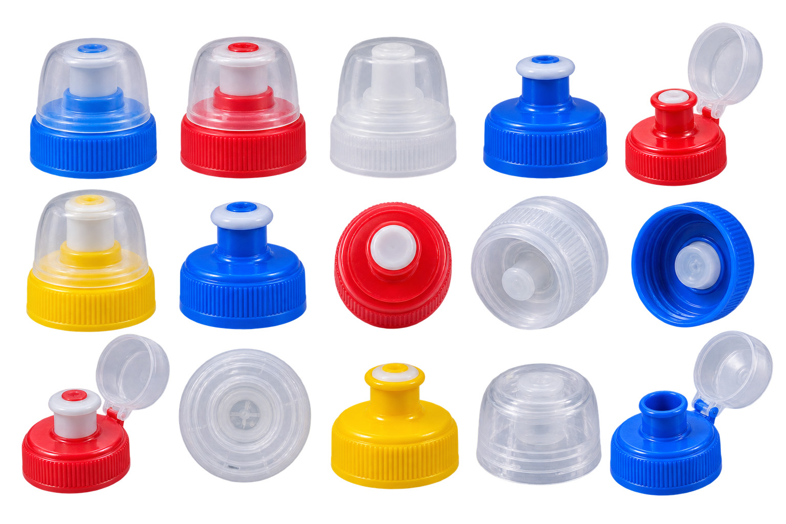
At cap-molds, we combine state-of-the-art fluid simulation, Swiss high-speed CNC machining, and decades of specialized closure mold expertise. Whether you require beverage, pharmaceutical, or specialized flip-top closure tooling, our engineering team delivers high-cavitation molds optimized for superior thermal balance, maximum uptime, and long-term operating profitability.